Unique Pump System, Kailash Industrial Complex, Vikhroli West
Gear pumps and centrifugal pumps are often evaluated side-by-side for the same fluid transfer application — and choosing the wrong type leads to a predictable pattern of underperformance, excessive energy use, or chronic maintenance failures. The decision goes deeper than a simple viscosity cutoff or pressure limit. It involves understanding how each pump's operating physics determines its response to real-world variables: changing viscosity with temperature, fluctuating system resistance, particle content, fluid shear sensitivity, and the cost of downtime when the pump fails. This guide covers the complete technical comparison — including performance mathematics that most pump selection guides skip — to give engineers and plant managers the specific knowledge needed to make the right choice first time. For product specifications, the gear pump (UA Series, 2–6000 LPM, up to 70 kg/cm², up to 100,000 cSt) and centrifugal pump (SS 304/316, up to 1890 LPM, up to 76 metres head) ranges from Unique Pump Systems cover the majority of Indian industrial fluid transfer requirements.
Read More: Gear Pump Guide
Every practical difference between gear pumps and centrifugal pumps follows directly from one fundamental difference in how each converts energy into fluid movement. Grasping this physics prevents the most common selection errors.
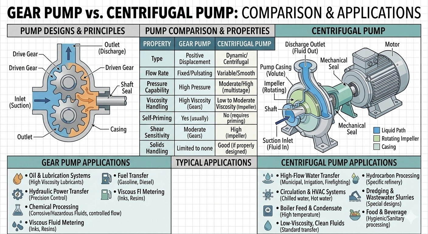
A gear pump moves fluid by physically enclosing a defined volume of fluid between the gear teeth and the pump casing, then transporting that enclosed volume from the suction port to the discharge port as the gears rotate. The fluid is not accelerated — it is carried. Two precision-machined gears (external type: two external spur or helical gears; internal type: a rotor and idler) rotate in mesh, creating expanding cavities at the suction side that draw fluid in, and collapsing cavities at the discharge side that force fluid out.
The defining characteristic of this positive displacement mechanism: for every revolution of the drive gear, a fixed geometric volume of fluid is displaced — regardless of what pressure is present at the outlet. If the discharge is blocked, pressure rises until something gives (a pipe fitting, a seal, or the relief valve). If viscosity doubles, the pump still displaces the same volume per revolution, though it requires more torque to do so.
A centrifugal pump imparts kinetic energy to the fluid using a rotating impeller. The impeller accelerates the fluid radially outward from its eye (centre) to its periphery through centrifugal force. This high-velocity fluid then enters the volute casing — a spiral passage that decelerates the fluid and converts its velocity into pressure energy (Bernoulli conversion). The resulting pressure differential between suction and discharge drives the fluid through the system.
The defining characteristic of this kinetic energy mechanism: pump output depends on the fluid's ability to be accelerated by the impeller. Anything that resists acceleration — high viscosity, entrained gas, low suction pressure, or operation far from the design speed — directly degrades performance. The pump does not force a fixed volume; it produces a pressure head that the system uses to drive flow. Flow rate is determined by the intersection of the pump curve with the system curve — not by the pump alone.
A centrifugal pump's H-Q curve (head vs. flow rate) is a downward-sloping line: maximum head at zero flow (shutoff head), declining to zero head at maximum flow (runout). The pump always operates at the point where this curve intersects the system resistance curve. This has three critical consequences that gear pump users never face:
A gear pump does not have an H-Q curve in the same sense. Its flow-pressure characteristic is nearly flat: flow rate changes only slightly as discharge pressure changes (due to internal slip — see below). For practical purposes, if you set the gear pump speed to X RPM, you get approximately X × displacement LPM regardless of whether the discharge pressure is 2 bar or 20 bar.
Gear pump performance is not perfectly constant with pressure. Internal slip — the leakage of fluid back from the high-pressure discharge side to the low-pressure suction side through the internal clearances between gears and casing — increases as discharge pressure increases. This reduces the net volumetric output slightly at higher pressures.
Volumetric efficiency is the ratio of actual flow to theoretical displacement flow:
For a well-designed gear pump at rated pressure: volumetric efficiency is typically 90–96%. At higher pressures or with worn clearances, it drops. Importantly, higher fluid viscosity reduces slip (thicker fluid leaks less through clearances), so gear pump volumetric efficiency actually improves with increasing viscosity — the opposite of a centrifugal pump.
| Fluid Viscosity (cSt) | Gear Pump Vol. Efficiency | Centrifugal Pump Overall Efficiency | Implication |
|---|---|---|---|
| 1–10 (water, solvents) | 85–90% (high slip — thin fluid leaks easily) | 70–80% (at BEP) | Centrifugal pump more efficient for low-viscosity service |
| 50–100 (light oil) | 90–94% | 55–70% (HI correction applied) | Approaching parity — evaluate both types |
| 200–500 (heavy oil, resins) | 93–96% | 35–55% (significant degradation) | Gear pump clearly more efficient |
| 1,000–5,000 (adhesives, paints) | 95–97% | 10–30% (often impractical) | Gear pump the only viable rotodynamic option |
| 10,000–100,000 (bitumen, rubbers) | 96–98% | Not viable | Gear pump with heating/steam jacket required |
No single parameter separates gear pumps from centrifugal pumps more decisively than fluid viscosity. The Hydraulic Institute (HI) viscosity correction factors for centrifugal pumps quantify the performance degradation that occurs as viscosity increases:
| Viscosity (cSt) | Flow Correction (CQ) | Head Correction (CH) | Efficiency Correction (Cη) | Power Draw Change | Decision Guidance |
|---|---|---|---|---|---|
| 1 (water) | 1.00 | 1.00 | 1.00 | Baseline | Either pump viable — centrifugal preferred for high flow, low pressure |
| 50 | 0.95 | 0.96 | 0.90 | +6% vs water | Minor degradation — centrifugal usually still acceptable |
| 100 | 0.90 | 0.92 | 0.81 | +11% | Noticeable — verify motor sizing; consider gear pump for pressure applications |
| 200 | 0.82 | 0.87 | 0.71 | +15% | Significant — centrifugal pump may underperform; gear pump recommended |
| 500 | 0.70 | 0.76 | 0.54 | +30% | Major degradation — gear pump strongly preferred |
| 1,000 | 0.57 | 0.65 | 0.37 | +54% | Severe — centrifugal pump borderline viable only at very low pressure |
| 5,000+ | <0.40 | <0.50 | <0.20 | Prohibitive | Gear pump only viable option |
Many process fluids change viscosity significantly with temperature — vegetable oils, polymer solutions, hot melt adhesives, bitumen, and lubricating oils all follow this pattern. When selecting between pump types, the selection must be valid across the full viscosity range the fluid will experience in service:
Gear pumps are high-pressure positive displacement pumps by nature. The UA Series from Unique Pump Systems is rated to 70 kg/cm² (approximately 70 bar / 1000 PSIG) — far beyond the capability of any standard centrifugal pump in the same size class. Standard industrial centrifugal pumps in single-stage configurations typically develop 15–50 metres of head (1.5–5 bar), and even multi-stage designs rarely exceed 100 bar.
The pressure capability difference reflects the fundamental physics: a gear pump directly forces fluid against whatever pressure is present; a centrifugal pump can only develop the head corresponding to the kinetic energy imparted by the impeller at a given speed. To double head from a centrifugal pump, you must either add stages or increase impeller speed — both add cost and complexity.
Gear pumps are inherently self-priming. As the gears rotate, the expanding cavities at the suction side create a true vacuum — no fluid in the pump is needed to generate the priming action. A gear pump can reliably lift fluid from 3–5 metres below the pump inlet and will prime from a completely dry state.
Standard centrifugal pumps are not self-priming — the impeller must be surrounded by fluid to generate the pressure differential needed to draw fluid in. A standard centrifugal pump with an empty casing can spin indefinitely without moving any fluid. Self-priming centrifugal pumps are available but require a priming chamber and are more expensive than standard designs.
Net Positive Suction Head (NPSH) is the defining suction-side limitation for centrifugal pumps. If the available NPSH (NPSHa) at the pump inlet drops below the pump's required NPSH (NPSHr), the fluid vaporises at the low-pressure zone inside the impeller — cavitation occurs. Cavitation causes impeller erosion, noise, vibration, and immediate performance loss.
Gear pumps are positive displacement pumps. While they can experience suction-side problems (cavitation-like damage from very high suction lift or very high speed with low-viscosity fluids), they do not have an NPSHr in the centrifugal pump sense. The main suction-side limitation for a gear pump is the maximum allowable inlet vacuum, which is typically much easier to satisfy than centrifugal pump NPSH requirements for the same duty.
| Suction Condition | Gear Pump Response | Centrifugal Pump Response |
|---|---|---|
| Low suction pressure / high suction lift | Handles up to 3-5m suction lift from dry start; performance reduces at extreme vacuum | Cavitates if NPSHa < NPSHr — impeller damage, noise, flow collapse |
| Air or gas in suction line | Continues to operate — pumps gas-liquid mixture at reduced volumetric efficiency | Loses prime and stops pumping — requires re-priming or flooding |
| Declining liquid level in source tank | Continues to pump until tank is empty; runs dry briefly without severe damage | NPSHa decreases as level drops; pump cavitates before tank is empty |
| Cold-start with high-viscosity fluid | Requires higher motor torque — flow is reduced; pump continues to operate | Motor may overload; pump may not develop required head at high viscosity |
| Variable or fluctuating suction pressure | Flow rate minimally affected — displacement is suction-pressure-independent | Operating point shifts on H-Q curve; flow and pressure both vary |
Many industrial fluids contain components that are physically damaged by the high shear forces generated inside a centrifugal pump impeller — the rapid acceleration and turbulence at the impeller vanes break up molecular structures, emulsion droplets, or suspended particles that must be preserved. Examples include:
Gear pumps — particularly internal gear pumps — generate much lower shear rates than centrifugal pumps. The fluid is moved gently by the meshing gears rather than being flung through an impeller at high velocity. For shear-sensitive fluids, the gear pump is almost always the correct choice.
Many high-viscosity industrial fluids (bitumen, hot melt adhesive, heavy fuel oil, chocolate, wax, resins) must be maintained at elevated temperatures to remain pumpable. At ambient temperature, they solidify or become too viscous to move. Gear pumps can be supplied with a steam jacket or hot oil jacket around the pump body, maintaining the fluid at the required temperature throughout the pump:
Gear pumps have very tight internal clearances between the gear teeth and the casing walls — these clearances are what prevent excessive slip and maintain volumetric efficiency. Hard abrasive particles that enter these clearances cause rapid wear, increasing clearance size, reducing efficiency, and eventually requiring a rebuild. For abrasive slurries, gear pumps are generally a poor choice unless the gear and casing materials are specifically hardened (hardened steel gears and wear plates are available).
Centrifugal pumps tolerate abrasive particles better in terms of continued operation, but the impeller and casing wear progressively — pump performance declines gradually as wear increases. For heavily abrasive slurries (mining, minerals, wastewater with grit), neither gear nor centrifugal pumps are ideal — centrifugal slurry pump designs with thick rubber or hardened metal impellers and casings are the specialist solution.
The most common method of controlling centrifugal pump flow is discharge throttling — partially closing a valve in the discharge line to increase system resistance and move the operating point left on the H-Q curve. This is simple and reliable but wastes energy — the pump still operates at full power but does less useful work.
The energy-efficient alternative is a Variable Frequency Drive (VFD) on the motor. The centrifugal pump's affinity laws describe how performance scales with speed:
Reducing speed to 80% of rated reduces flow to 80%, head to 64%, and power to 51%. VFD control of centrifugal pumps in variable-flow systems typically saves 20–50% of motor energy compared to throttle control — one of the most impactful energy efficiency measures in industrial pump systems.
Gear pump flow is directly proportional to shaft speed — halving the speed halves the flow, linearly and precisely. This makes gear pumps ideal for metering and dosing applications where a specific flow rate must be delivered accurately. Flow control methods:
Both gear pumps and centrifugal pumps require a shaft seal where the rotating drive shaft passes through the pump casing. However, the sealing requirements and available options differ significantly.
| Sealing Consideration | Gear Pump | Centrifugal Pump |
|---|---|---|
| Shaft speed at seal face | Low to moderate — gear pumps run at 50–1500 RPM; seal face velocity is lower than centrifugal pumps of equivalent output | High — centrifugal pumps run at 1450–3000 RPM; higher seal face velocity accelerates wear |
| Pressure at seal | High — gear pumps develop high discharge pressures; balanced mechanical seal required above 10–12 bar | Moderate — most single-stage centrifugal pumps operate within unbalanced seal capability; balanced seal for high-head multistage |
| Gland packing option | Viable at lower pressures and for non-hazardous fluids — gear pump's lower speed makes packing a practical option | Less practical — higher shaft speed accelerates packing wear and heat generation |
| Magnetic coupling (sealless) | Available — magnetically coupled gear pumps eliminate the shaft seal entirely for toxic or high-purity fluid service | Available but less common in gear pump sizes — canned motor centrifugal pumps are the standard sealless centrifugal option |
| Seal environment (fluid film) | Seal faces see process fluid directly — fluid lubricity affects seal life; flush plans may be needed for low-lubricity fluids at high pressure | Same — seal faces require fluid film lubrication; loss of prime destroys seal within seconds by removing the fluid film |
When handling water or low-viscosity fluids at or near the centrifugal pump's Best Efficiency Point, centrifugal pumps are more efficient than gear pumps. A well-designed centrifugal pump at BEP achieves 70–82% hydraulic efficiency; an equivalent gear pump typically achieves 85–92% volumetric efficiency but has additional mechanical losses in bearings and gear mesh friction, giving an overall efficiency of 75–88% depending on design and viscosity.
For large-volume, low-viscosity continuous service (water supply, cooling circuits, utility fluid), the centrifugal pump's efficiency advantage is real and economically significant. A 1% improvement in pump efficiency in a 100 kW pump running 8,000 hours/year saves approximately 8,000 kWh/year — around Rs. 64,000 annually at Rs. 8/kWh.
The centrifugal pump's efficiency advantage disappears — and reverses — under three conditions:
Application A: Clean water, 50 LPM, 4 bar, continuous duty, 8 hours/day, 300 days/year
| Cost Element | Centrifugal Pump | Gear Pump |
|---|---|---|
| Capital cost (pump + motor) | Rs. 35,000 – Rs. 60,000 | Rs. 55,000 – Rs. 90,000 |
| Energy cost/year (at efficiency advantage) | Rs. 12,000 – Rs. 18,000 | Rs. 15,000 – Rs. 22,000 |
| Maintenance (seals, bearings)/year | Rs. 5,000 – Rs. 12,000 | Rs. 4,000 – Rs. 8,000 |
| 5-year total | Rs. 1,25,000 – Rs. 2,10,000 | Rs. 1,74,000 – Rs. 2,90,000 |
| Verdict | Centrifugal pump lower 5-year cost | Higher cost for this application |
Application B: Polymer solution at 800 cSt, 15 LPM, 8 bar, 8 hours/day, 300 days/year
| Cost Element | Centrifugal Pump | Gear Pump |
|---|---|---|
| Capital cost (pump + motor — centrifugal needs larger motor for viscosity) | Rs. 65,000 – Rs. 1,10,000 | Rs. 55,000 – Rs. 85,000 |
| Energy cost/year (centrifugal at ~35% eff. vs gear pump at ~90%) | Rs. 55,000 – Rs. 85,000 | Rs. 22,000 – Rs. 35,000 |
| Downtime/repair (centrifugal chronic cavitation failures at high visc.) | Rs. 30,000 – Rs. 80,000/year | Rs. 5,000 – Rs. 15,000/year |
| 5-year total | Rs. 5,50,000 – Rs. 11,50,000 | Rs. 1,90,000 – Rs. 3,50,000 |
| Verdict | Far higher — centrifugal not suitable | Gear pump correct choice |
| Parameter | Gear Pump | Centrifugal Pump |
|---|---|---|
| Operating principle | Positive displacement — fixed volume per revolution | Kinetic energy — velocity converted to pressure via impeller |
| Flow characteristic | Constant — nearly independent of discharge pressure | Variable — flow decreases as system pressure increases |
| Max viscosity (practical) | Up to 100,000 cSt with appropriate speed and materials | ~200–300 cSt before significant efficiency loss; not viable above 1,000 cSt |
| Max pressure (typical single stage) | Up to 70 bar (700 m head equivalent) — UA Series to 70 kg/cm² | 5–50 metres head (0.5–5 bar) single stage; multi-stage to ~100 bar but costly |
| Self-priming | Yes — inherently self-priming from dry state | No (standard); self-priming designs available at premium cost |
| Efficiency at BEP, water service | 75–88% overall | 70–82% at BEP — advantage over gear pump for low-viscosity service |
| Efficiency at 500 cSt viscosity | 90–95% (improves with viscosity) | ~40–50% (degrades severely with viscosity) |
| Flow control method | Speed control — precise, linear; bypass valve; relief valve for protection | Discharge throttle valve (wasteful) or VFD (energy-efficient); affinity laws apply |
| Shear sensitivity | Low shear — suitable for shear-sensitive fluids | High shear at impeller — destroys emulsions, polymers, biological materials |
| Abrasive fluids | Poor — tight clearances wear rapidly; hardened gears available for moderate abrasion | Better tolerance — impeller wears gradually; dedicated slurry designs available |
| Self-priming from dry state | Yes | No (standard design) |
| Relief valve required | Yes — mandatory; pump will over-pressurise without it | No — pump cannot exceed shutoff head regardless of discharge condition |
| Minimum flow required | No — can run at any flow including near-zero with speed control | Yes — running below minimum flow causes heat buildup and seal damage |
| Noise level | Low-moderate: 60–75 dB(A) — helical gears quieter than spur | Low-moderate: 60–75 dB(A) — quieter at BEP, noisier when cavitating |
| Steam jacket option | Yes — standard for high-viscosity hot fluids (bitumen, wax, hot melt adhesive) | Not practical for the required temperatures and configurations |
| Capital cost | Moderate–High — precision machining of gears and casings | Low–Moderate — simpler internal geometry; economical for large flow sizes |
| Maintenance primary wear items | Gears, shaft seals, bearings — long intervals with clean fluids | Mechanical shaft seal (primary failure point), bearings, impeller (wear in abrasive service) |
| Best application profile | High viscosity, high pressure, precise metering, shear-sensitive fluid, self-priming required, hot or cold fluid extremes | High flow, low-viscosity, clean fluid, continuous duty at stable conditions, energy cost matters |
Answer each question in sequence. The first decisive answer determines the pump type:
| Question | If YES | If NO |
|---|---|---|
| Is fluid viscosity above 200 cSt at any point in the operating temperature range? | Gear pump — centrifugal efficiency penalty is unacceptable above this level | Continue |
| Does the application require discharge pressure above 6 bar from a single pump stage? | Gear pump — centrifugal pump requires expensive multi-stage design | Continue |
| Is the fluid shear-sensitive (polymer, emulsion, biological, food structure)? | Gear pump — centrifugal impeller shear damages the product | Continue |
| Is the pump required to self-prime from a dry state or handle intermittent suction? | Gear pump — inherent self-priming capability | Continue |
| Must fluid temperature be maintained by jacketing the pump body? | Gear pump — steam or hot oil jacket available as standard option | Continue |
| Is precise, repeatable flow metering required (dosing, batch transfer)? | Gear pump with speed control — linear flow vs. speed relationship is ideal for metering | Continue |
| Is the application high-flow, low-pressure, clean fluid, stable suction, continuous duty? | Centrifugal pump — energy and capital cost advantage is compelling | Gear pump — more robust across variable conditions |
| Is VFD control being used and energy cost is the primary concern? | Centrifugal with VFD — affinity cube law gives excellent energy savings at part load | Gear pump — simpler and more reliable for variable-speed operation without VFD optimisation |
In terms of flow and pressure — often yes. But the operating characteristics change: you gain self-priming, pressure stability, and viscosity tolerance; you lose smooth continuous flow (gear pumps have slight flow ripple), and you add a mandatory relief valve requirement. For high-viscosity or high-pressure applications, the replacement is beneficial. For clean water at high flow, the centrifugal pump is the better long-term choice.
Because centrifugal pump flow is determined by the H-Q curve intersection with the system curve — not by the pump alone. Closing the discharge valve steepens the system curve, which shifts the operating point left (higher head, lower flow). A gear pump would not respond this way — it continues to deliver nearly the same flow regardless of valve position, building pressure instead of reducing flow, until the relief valve opens.
The practical crossover point is approximately 150–300 cSt, depending on the specific pump sizes and application requirements. Below 150 cSt, centrifugal pumps are usually more efficient and economical. Above 300 cSt, gear pump efficiency and reliability advantages are clear. Between 150–300 cSt, both types can work — calculate the total cost of ownership for your specific duty cycle to determine which is better for your application.
Yes. A check valve prevents backflow but does not limit maximum pressure. If the discharge is blocked downstream of the check valve, the gear pump will build pressure until something fails. The relief valve is the only protection against over-pressurisation and is non-negotiable for any gear pump installation.
Unique Pump Systems manufactures both gear pumps (UA Series, 2–6000 LPM, up to 70 kg/cm², viscosity up to 100,000 cSt, sizes 3/8" to 8", with steam jacket and magnetically coupled options) and centrifugal pumps (SS 304/316, 12 mm to 100 mm port, up to 1890 LPM, up to 76 metres head) for the full range of industrial fluid transfer applications in India. For guidance on which pump type suits your specific fluid, viscosity, pressure, flow, and installation conditions, contact our application engineering team.
Gear pumps and centrifugal pumps are differentiated by one fundamental principle: gear pumps are positive displacement machines that force a fixed volume of fluid per revolution regardless of system pressure; centrifugal pumps convert impeller velocity into pressure and deliver variable flow determined by the system curve intersection. This single difference drives every practical performance distinction: gear pumps excel at high viscosity, high pressure, precise metering, self-priming, and shear-sensitive fluid handling; centrifugal pumps excel at high flow, low viscosity, energy-efficient continuous duty at stable operating conditions.
The most reliable selection rule: check the fluid viscosity first. Above 300 cSt at any operating temperature, the gear pump is almost always the correct choice. Below 100 cSt in stable, high-flow, continuous service, the centrifugal pump delivers lower capital and energy cost. Between 100–300 cSt, calculate total cost of ownership for both options at the actual duty cycle before deciding.